About us
Our historyEngineering with a pedigree — since 2010
Our mission5% of deployment profits go to charity
Why usSix reasons to choose H-corePLC®
Since 2010
Automation engineering office
Koszalin · industrial PLC controllers and deterministic algorithms.
Discover our historyB2C · AQUA Contra
AQUA Contra overviewHow the flow guard works
AQUA Contra DIYSelf-installation · launch April 2027
AQUA Contra BASICWith RE distribution board · launch April 2027
B2B · H-corePLC®
H-corePLC® overviewA platform for businesses and investments
H-corePLC® szychtaConstruction sites · launch Dec 2027 · presentation
H-corePLC® officeOffice and residence · launch Q3 2028
PLC2 for risersMulti-apartment buildings · pre-launch
Not sure which to choose?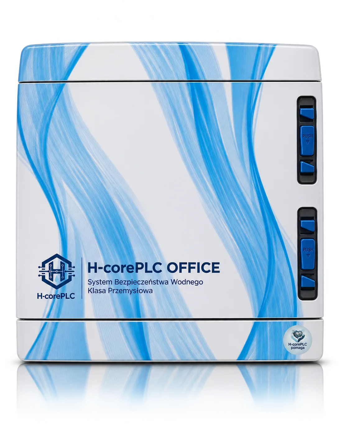 Book a presentation
Home or business?
Compare the systems or book a presentation.
Book a presentationComparisons and questions
Flow vs spot leak detectorWhy react to the cause
FAQFrequently asked questions
Academy
Spot leak detector vs flow measurement
A new technical article comparing the architectures.
Read the articleFor partners
Property developersOne system from construction to handover
WholesalersAQUA Contra kits in your range
Design officesDiagrams and technical conditions
InstallersInstallation with a commissioning report
Live demo
Invite us for a presentation
We will demonstrate the system on a test rig — at your site or in Koszalin.
Book a presentationH-corePLC®
Home/Cooperation/Design offices
Partnership
Design offices
Guidelines for designing water installations with H-corePLC® flow-based flood protection.
01Book a presentation
02Property developers
03Wholesalers
04Design offices
05Installers
Draft text — prepared on the basis of the technical specification. Subject to client approval.
Partnership
Design offices.
Flow-based protection is installed centrally at the water service connection — downstream of the main water meter. This way it monitors the entire installation, including concealed and underfloor sections, not just the spots fitted with sensors.
Below we have compiled the parameters and requirements worth taking into account at the design stage. On request, we will prepare a node diagram for a specific project.
Node diagrams
Sample hydraulic and electrical layouts for your design — for apartments, offices and risers.
Technical requirements
Specification, installation requirements and scope of responsibility in a single document.
Consultations
Support from an automation engineer in selecting operating modes and thresholds.
Open technology
Standard PLC controllers (Siemens LOGO!, Eaton) and common installation components.
Details
Design parameters
01
Good to know
Requirements and good practice.
02
Node components
EZ solenoid valve, water meter with a pulse transmitter, mesh filter, non-return valve, flood probe — according to the manufacturer's diagram.
Service bypass
A parallel bypass with a manual valve sealed in the closed position.
Flood probe
Electrodes 2–3 mm above the floor, at the lowest point of the wet zone, in the path of the water run-off.
RE distribution board
Space for the control cabinet with service access.
Process
How do we start working together?
03
01
Enquiry
Building type, number of units, service connections.
02
Consultation
Selection of modes, thresholds and node locations.
03
Materials
Node diagram, specification, data sheets.
04
Supervision
Support during acceptance and commissioning.
Questions
Frequently asked questions.
04
Where is the node installed?
Centrally at the water service connection, downstream of the main water meter — so that it monitors the entire installation in the building.
Does the system replace leak detectors?
It does not rule them out. Spot probes are wired directly into the PLC controller as an additional, hard shut-off priority.
Are data sheets available?
Yes — we prepare data sheets and diagrams for each specific project. The technical specification can be downloaded from the footer.
H-corePLC®
Deterministic protection
for your water system.
for your water system.
Biuro Inżynierskie Automatyki, Koszalin
+48 000 000 000
kontakt@h-coreplc.pl
Systems
AQUA Contra — overview
AQUA Contra DIY
AQUA Contra BASIC
H-corePLC® — overview
H-corePLC® szychta
H-corePLC® office
PLC2 for risers
Academy
State of the art
Case study
Flow vs spot leak detector
FAQ
About us
Our history
Our mission
Why us
Service
Partnership
Book a presentation
Property developers
Wholesalers
Design offices
Installers
Terms of sale
PDF · version 1.0
Technical, environmental and installation requirements
PDF · H-core technical specification
Privacy policy
GDPR · page
H-corePLC®
© 2026 H-corePLC® & AQUA Contra. All rights reserved.Terms · Privacy policy · Cookies